Radial Motor Cores mainly use electrical steel, the common default, along with soft magnetic composites and, in some designs, cobalt-iron alloys or amorphous metal. Each family offers a distinct balance of magnetic performance, mechanical behavior, and processing route.
Speed, efficiency targets, cost, and production volume drive the final material choice. Shunge supplies Custom Radial Motor Core options across all of these material families, so designers can match the core to the application rather than compromise.
Key Takeaways
-
Electrical steel is the most common material for radial motor cores. It offers low iron loss and works well for many motor types.
-
Soft magnetic composites allow flexible 3D flux paths. They suit compact or complex rotor designs.
-
Cobalt-iron alloys provide high magnetic strength for high-performance motors. They cost more and need careful heat treatment.
-
Amorphous metal reduces iron loss sharply. It fits stators with tight space limits but limits shape freedom.
-
Choose core materials based on measured loss data under real drive conditions. Speed, efficiency, cost, and volume guide the final decision.
What Radial Motor Cores Must Do
Flux Path Basics
A radial motor core guides magnetic flux in a circular path. The flux crosses the air gap from the rotor to the stator in a radial direction, meaning along the radius of the shaft. The stator teeth collect this flux and carry it through the yoke, then back to the next tooth. The core acts as a low-resistance road for the magnetic field, so the motor can build strong torque without wasting energy.
Lamination stacking is common because a solid steel block would let eddy currents circulate freely. Thin insulated sheets break those current loops. Each sheet carries flux along its plane, and the insulation blocks current from jumping between sheets. Stacking many thin laminations therefore keeps iron loss low while preserving the flux path. This construction also suits high-volume stamping, which keeps unit cost down.
Key Material Demands
A core material must satisfy five demands at once. High permeability lets the material carry flux with a small magnetizing current. Low iron loss keeps the core cool and protects efficiency, especially at high switching frequencies. Mechanical strength matters because the rotor spins fast and the stator must hold tight tolerances. Cost and manufacturability decide whether a design can reach production at all.
No single material wins on every point, so engineers trade one property against another. A high-permeability grade may cost more or stamp with more difficulty. A low-loss powder may carry less flux per unit volume. Axial and radial flux motors share the same electromagnetic principles, so material lessons transfer between the two topologies. A grade that reduces loss in an axial machine usually behaves the same way in Radial Motor Cores.
Electrical Steel For Radial Motor Cores
Composition And Properties
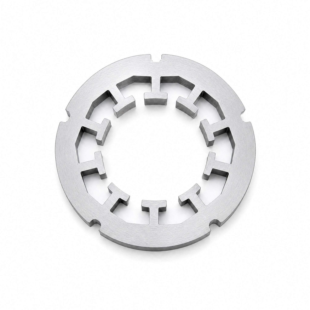
Non-grain-oriented (NO) electrical steel, often called silicon steel, is the common default for stacked Radial Stator Lamination Core builds. Manufacturers add a small percentage of silicon to iron, then roll and anneal the sheet to control grain structure. The silicon raises electrical resistivity, which suppresses eddy currents. The result is a material with excellent magnetic properties and low iron loss. Thin gauge and tight thickness tolerance help designers pack more laminations into a given stack height.
Grain-oriented (GO) steel offers a different trade. Its grains align in one direction during rolling, so magnetic permeability along that direction is significantly higher than in NO grades. The production route is more complex and costly, and the benefit appears only when flux runs along the rolling direction. Radial cores carry flux in many directions, so GO steel suits only selected geometries.
Where It Fits Best
Core material decisions should rest on measured loss data, not datasheet headlines. Loss depends on frequency, flux density, and sheet thickness together. A grade that looks strong at one operating point may lose its edge at another. Engineers who test candidate grades under real drive conditions choose better, and electrical steel laminations remain an effective solution for many motor cores.
Typical applications include traction motors, industrial pumps and fans, compressors, and household appliances. These machines run at moderate to high speed and reward the low loss and mature stamping supply chain of silicon steel. Shunge supplies Custom Radial Motor Core options in this family, with lamination stamping and stacking matched to the customer's drawing. Designers working on Radial Motor Cores can specify NO grades for general duty or discuss GO grades where the flux path allows.
Soft Magnetic Composites And Specialty Alloys
SMC Composition And Fit
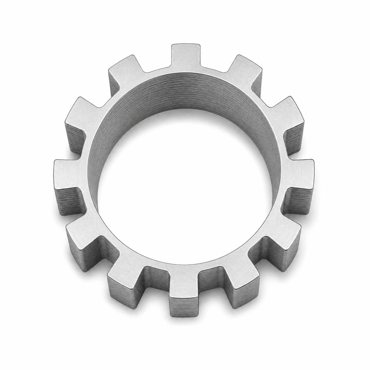
Soft magnetic composites (SMCs) start as iron powder. Each particle carries an electrically insulating coating. Manufacturers press the coated powder into a net shape and cure the binder. The insulation sits between particles, so eddy currents stay trapped inside each grain. This structure allows 3-dimensional flux paths in radial flux motor cores. Designers can route flux axially, radially, or diagonally without fighting the grain direction of a rolled sheet.
SMC rotors can help save electric motor end costs. A pressed rotor needs little machining and few stacking steps. The powder route also suits complex geometry, so parts that would need several laminations become one solid piece. SMCs fit best in motors with moderate flux density, higher pole counts, and space-limited rotors. They also serve claw-pole machines and small appliances. Shunge offers Custom Radial Motor Core designs in this family for buyers who need shaped flux paths.
Cobalt-Iron And Amorphous Options
Cobalt-iron alloys serve high-performance cases. The cobalt addition pushes saturation flux density well above that of plain silicon steel. A designer can therefore shrink the core or raise torque for the same volume. These alloys cost substantially more and demand careful heat treatment, so they appear in aerospace, racing, and compact high-torque machines.
Amorphous metal cut cores target stator iron loss. The metal solidifies without a crystal lattice, which raises resistivity and cuts eddy current loss sharply. Thin ribbon and cut-core construction save motor space because the core needs less cooling hardware. The trade is limited shape freedom and higher material cost.
The table below compares the main options on performance, application fit, compliance, and cost. Compliance refers to classification under IEC 60404, the public standard for magnetic materials.
|
Material |
Magnetic performance |
Best application fit |
Regulatory compliance |
Relative cost |
|---|---|---|---|---|
|
NO electrical steel |
High permeability, low iron loss |
Traction, pumps, fans, appliances |
IEC 60404 classification |
Low to moderate |
|
GO electrical steel |
Significantly higher permeability along rolling direction |
Directional flux paths only |
IEC 60404 classification |
Moderate to high |
|
Soft magnetic composite |
Moderate permeability, 3D flux, low eddy loss |
Shaped rotors, claw-pole, compact designs |
IEC 60404 classification |
Moderate |
|
Cobalt-iron alloy |
Highest saturation flux density |
Aerospace, racing, compact high torque |
IEC 60404 classification |
High |
|
Amorphous metal |
Very low iron loss |
Stators with tight space limits |
IEC 60404 classification |
High |
Each family earns its place. Measured loss data under real drive conditions should settle the final choice for Radial Motor Cores.
Radial Motor Cores mainly use electrical steel, soft magnetic composites, and sometimes cobalt-iron alloys or amorphous metal. Each family brings its own balance of magnetic performance, mechanical behavior, and processing route.
The right choice depends on the specific motor requirements: speed, efficiency, cost, and volume. Measured loss data under real drive conditions should guide the decision, because datasheet headlines rarely tell the full story.
Designers can contact Shunge for a Custom Radial Motor Core matched to their application. The team supports lamination stamping, powder-based designs, and specialty alloy options, so each project starts from its own performance targets.
FAQ
Why does electrical steel dominate radial motor core production?
Silicon steel combines strong magnetic properties with low iron loss, and the stamping supply chain is mature. Lamination stacking keeps eddy currents low. Shunge builds Custom Radial Motor Core options in this family for traction, pump, fan, and appliance motors.
When does a designer choose soft magnetic composites instead?
SMCs suit shaped flux paths. Insulated iron particles allow 3-dimensional flux in radial flux motor cores, and a pressed rotor needs little machining. These materials fit compact rotors, claw-pole machines, and designs with moderate flux density.
Do cobalt-iron alloys justify their higher cost?
They do in high-performance cases. Cobalt-iron carries a higher saturation flux density than silicon steel, so a smaller core delivers the same torque. Aerospace and racing machines accept the cost and the careful heat treatment.
How should a team pick between these material families?
Measured loss data under real drive conditions should settle the choice. Speed, efficiency targets, cost, and volume all shape the answer. Designers can request a Custom Radial Motor Core from Shunge and compare candidate grades on their own duty cycle.
What role does amorphous metal play in stator cores?
Amorphous metal cuts iron loss sharply because its non-crystalline structure raises resistivity. Cut-core stators save space by needing less cooling hardware. The trade is limited shape freedom and higher material cost, so it fits space-limited stators.